Demos: 6C-12 Resonance
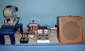
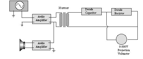
A circuit consisting of an inductance, a capacitor and a resistor is series is driven by an audio oscillator. The coupling is through a transformer whose secondary is the inductance of the resonant circuit. Resonance is observed by measuring the voltage across the resistance while the audio frequency is varied, watching for the maximum voltage across the resistance. A projection voltmeter allows for better viewing and an auxiliary amplifier and loudspeaker allows one to hear the resonant frequency.
Directions: Typical settings:
f
L
C
R
Suggestions for Presentation: Discuss the conditions for resonance and why one wants to measure the voltage output across R (you are measuring iR, so this measurement gives a direct indication of the current in the circuit).
Applications: Various resonant circuits in electronics.
Last Updated: Nov 30, 2023 11:25 AM