Demos: 6C-02 RC Circuit Analysis
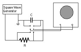
The voltage across a capacitor and a series resistor in an RC circuit is demonstrated with the help of a square-wave generator and a large oscilloscope.
Directions: We suggest an oscillator frequency of about 700 Hz with R = 10K and C = 0.01 mF. A decade resistance box and a variable capacitor box are also available. The DPDT switch allows for switching between the resistor and capacitor.
Suggestions for Presentation: Discuss the RC circuit parameters and focus on the effects of changing R and/or C. Make sure the students understand what the trace of the oscilloscope is showing.
Applications: Electronic circuits
Last Updated: Nov 30, 2023 11:25 AM