| |
| Search Engines and Directory: |
|
|
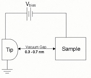
To use this technique, substrates must be relatively
flat and electrically conducting. To obtain an image of a substrate,
the substrate is moved until it is approximately 0.3 –
1.0 nm away from a probe tip usually made of W or a Pt-Ir alloy.
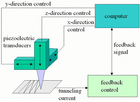
The tip is attached to a piezodrive. There are three mutually
perpendicular piezoelectric transducers: x piezo, y piezo, and
z piezo. These transducers expand or contract in a controlled
way upon application of an applied voltage. By applying a saw
tooth voltage signal on the x piezo and a slower voltage ramp
on the y piezo, the tip can be made to raster in a controlled
fashion in the xy plane.
Using the z piezo, the tip and substrate can be brought close
enough to each other so that the electronic wave functions in
the tip overlap with the electronic wave functions in the substrate.
Under these conditions, an applied bias voltage causes current
to flow. Such a current is quantum mechanical phenomenon and
is called tunneling current.
The tunneling current is amplified and changed to a voltage
by a high-gain, low noise preamplifier, and then compared to
a reference value. The difference is amplified and used as a
feedback signal to drive the z piezo. The phase of the amplifier
is chosen to provide negative feedback. When the tunneling current
is larger than the reference value, the z piezo tends to withdraw
the tip from the sample and vice versa. Therefore an equilibrium
z position is established and kept during the whole scanning
process.
The voltage on the z piezo is recorded, changed to height value
(in nanometers) using the calibration values, then stored to
provide a constant current contour of the sample. The magnitude
of the current depends strongly on the separation between the
tip and the sample, which results a 0.01 nm vertical resolution.
The lateral resolution is determined by the single atom at the
end of the tip in ideal case to be 0.1 nm.
|