Theory: In many instances direct change of the output voltage from
a power supply is not practical (as when many experiments are being powered by the same
source) or possible (as when batteries are used). Thus a device is needed which will
produce a range of output voltages from a constant input voltage. The following material
discusses the theory of one such device, the "voltage divider".

Suppose a resistance wire of total resistance R is connected
between the terminals of a power source as shown in Fig. 1. Then the constant
potential Vo causes a constant current I through R where ![]() . Suppose also, for
simplicity, that the wire is uniform, i.e., that the resistance per unit length is a
constant,
. Suppose also, for
simplicity, that the wire is uniform, i.e., that the resistance per unit length is a
constant, ![]() . Then the
resistance of a portion of wire of length x is
. Then the
resistance of a portion of wire of length x is
![]() .....
(1)
.....
(1)
But the current through the circuit is a constant, so the voltage drop across a length x, Vxis
![]() ......(2)
......(2)
In words, the voltage drop across a portion of wire of length x is equal to the
voltage drop Votimes the ratio of x to the total length L.
Since x can be varied from 0 to L it can easily be seen that Vxgoes
from 0 to Vo. In practice x is almost always measured
starting from one end of the resistance wire as shown in Fig. 1
Although the formula for Vx as a function of x is strictly valid
only for a wire whose resistance per unit length, ![]() , is constant, it is easy to see that
qualitatively Vx depends directly on x even if
, is constant, it is easy to see that
qualitatively Vx depends directly on x even if ![]() is not
constant. In any case Vx may be varied from 0 to Vo.
is not
constant. In any case Vx may be varied from 0 to Vo.
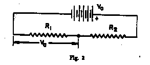
It is also possible to construct a voltage divider from fixed resistors if the objective
is simply to obtain some constant potential Vc which is less then Vo
. In this case the voltage divider would be as shown in Fig. 2.

R1 and R2 are fixed resistors and are chosen so that
![]() .....
(3)
.....
(3)
(Derive this equation, starting with the fact that the current through R1 + R2 is given by
![]() .....(4)
.....(4)
Note that if the divider is used to supply current to an exterior circuit, these simple relations for Vx or Vc do not hold. The potential supplied will then depend on the resistance of the exterior circuit (load).
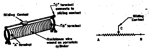
In our experiments a 33 ![]() slide-wire resistor is frequently used as a voltage divider. Fig.
3 shows pictorially and schematically the corresponding elements of the voltage
divider.
slide-wire resistor is frequently used as a voltage divider. Fig.
3 shows pictorially and schematically the corresponding elements of the voltage
divider.

Figure 3
Procedure: For parts (a) through (e) you will choose and assemble the appropriate
circuit on the basis for our previous discussion. By adjusting the sliding contact on the
33 ![]() slide-wire resistor you
can vary V and I. Take at least four pairs of (V,I) data for each
resistance you measure, more for those which are non-ohmic. Then graph V vs. I,
including estimated error bars, for each resistance. The experiment is not complete until
you have graphed the data.
slide-wire resistor you
can vary V and I. Take at least four pairs of (V,I) data for each
resistance you measure, more for those which are non-ohmic. Then graph V vs. I,
including estimated error bars, for each resistance. The experiment is not complete until
you have graphed the data.
(a) Select any two resistances on the resistance board and take V and I data
for each one individually. Since they are ohmic R = the slope of the V vs. I
graph (Prove). Use this to calculate R.
(b) Combine these two resistances in parallel and determine the resulting R as in
(a). Compare with the value obtained from ![]() .
.
(c) Combine the two resistors in series and determine the resulting R as in (a).
Compare with ![]() .
.
(d) Replace the resistance board by the diode and the fan-type ammeter by the multimeter.
Start with the multimeter range set to 500 ma. If you cannot get a measurable
current on that scale work your way down to more sensitive scales. Do not exceed 50 ma
of current through the diode! Record your results. Then reverse connections to the
diode and repeat the measurements. Graph the results of both set-ups on one graph,
arbitrarily associating -I and -V with one diode direction and +I and
+V with the other.
(e) Replace the diode by the light bulb. Measure V and I from V = 0
to V = 12V. Plot the log of the power dissipated
(P = VI) vs the log of the resistance R of the bulb. Can you
deduce a formula expressing the relationship between P and R from this plot?