Purpose: The purpose is to learn the definitions of static and dynamic resistance
and a method of resistance measurement. You will also learn the design and construction of
voltage dividers, ammeters and voltmeters.
Reference: Halliday, Resnick and Krane, Chapter 32. An
excellent outside source is University Physics, Sears and Zemansky (7th Ed.), articles
28-4, 29-1 and 29-3. Serway; Chap. 27, 28
Supplies: Bring note or data paper, plenty of graph paper, a straight edge and
a calculator.
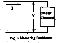
Theory: Suppose we have a circuit element as shown in Fig. 1 with current I
through it and a voltage drop V across it. Then its static resistance R
is defined by
(1) R=V/I.
R is not necessarily a constant if Iand V change. In dealing with
components for which R varies, it is sometimes useful to work with the dynamic
resistance r, defined by :
(2) r=dV/dI

At this point it should be emphasized that equation (1) is not Ohm's Law.
Rather, Ohm's Law is the special case of (1) when R is a constant,
independent of I. Fig. 2 is a graph of V vs. I for both an
ohmic (R = constant) and non-ohmic resistor. Note that for the non-ohmic resistor
both R and r vary as a function of I. The curve for R1 gives a
constant value for the static resistance no matter where you choose your points for
calculation. Since the curve for R1 is a straight line through the origin, this
value for the static resistance is also the slope of the line and hence equals the dynamic
resistance r1. The curve for R2 is not a straight line and indicates
non-ohmic behavior. Both static and dynamic resistance values vary depending on which
points are chosen for calculation. For several points on R2 the values of R2
and r2 are calculated in Table 1
Table 1

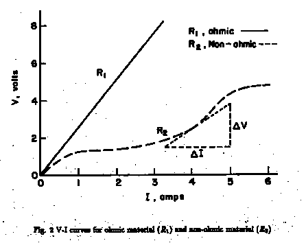
Fig2.
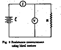
The definition of R suggests an experimental method for determining R. Fig.
3 shows an idealized set up, where the resistance of the voltmeter, RV,
is infinite and the resistance of the ammeter RAis zero. Then R
is simply given by equation (1) where V and I are the voltmeter and
ammeter readings.
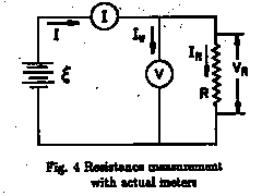
When actual meters are used it is found that RV is not infinite and RAis
not zero, although both are ohmic. In order to function, both meters use current to
operate and thus there are potential differences across the meters. To see the result of
this refer to Fig. 4. The voltage as read on the voltmeter is designated V
and the current through the ammeter is I.
Subscripts refer to corresponding elements of the circuit. The voltmeter measures the
potential difference (voltage drop) across R,
![]() (3)
(3)
But since RV < ![]() there is now a current IV through the voltmeter and
thus the ammeter measures the sum of the resistor and voltmeter currents,
there is now a current IV through the voltmeter and
thus the ammeter measures the sum of the resistor and voltmeter currents,
![]() (4)
(4)
The desired value of R = VR/IR so we solve (4) for IR
and divide the result into (3) obtain
![]() (5)
(5)
Since the voltmeter is ohmic it is useful to write ![]() and substitute in (5) to get
and substitute in (5) to get
![]() (6)
(6)
It is obvious that to determine R with high accuracy using the circuit in Fig. 4
we must know RV and use equation (6)) instead of (1).
An alternate circuit is shown in Fig. 5. Now the ammeter measures only the current
through the resistor,
![]() (7)
(7)
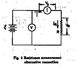
But the voltmeter now measures the total voltage drop across the ammeter and resistor
together,
![]() (8)
(8)
Again we want ![]() , so we
solve (8) for VR and divide the result by (7)) to get
, so we
solve (8) for VR and divide the result by (7)) to get
![]() (9)
(9)
But ![]() , so
, so
![]() (10) This time if
we want accurate values of R we must know RAand use (10)
instead of (1).
(10) This time if
we want accurate values of R we must know RAand use (10)
instead of (1).
To choose your experimental circuit you should know RV and RA for
your equipment and should have some idea of the value of R. Then if R << RV
you can use the diagram in Fig. 4 and calculate R = V/I, neglecting the
correction. If R >> RA use the diagram in Fig. 5 and
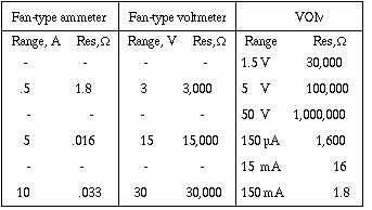
neglect the correction. Table 2 gives the resistances for the meters you will be
using.
TABLE 2
Apparatus: Fig. 6 shows the major items pictorially along with the schematic
symbol in some cases. The letters at various terminals correspond to the letters in the
schematic diagrams which follow.
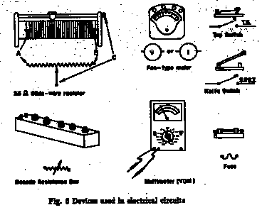
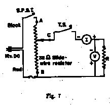
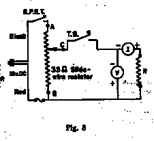
The circuits in Figs. 4 and 5 are not complete enough to be flexible
experimentally or to protect the equipment. Figs. 7 and 8 show the complete
versions of 4 and 5, respectively. The 33 ![]() slide-wire resistor is used as a voltage divider
so you can vary the voltage applied to the measuring circuit. Note that the circuit in Fig.
7 differs from that in Fig. 8 by only one connection, viz the point at which
the voltmeter is connected to the ammeter. It is not necessary to completely tear
down one circuit to build the other - just change the voltmeter connection. The fuse and
a tap switch are included to protect the ammeter from too large currents. To
avoid blowing fuses and damaging meters, start with the slide on the slide wire closer to
end B than to end A, make momentary contacts until you are sure the meters
will take the current, and use the less sensitive (higher) scales on the meters. Once
contacts are made you may reconnect the meters to more sensitive scales where feasible.
slide-wire resistor is used as a voltage divider
so you can vary the voltage applied to the measuring circuit. Note that the circuit in Fig.
7 differs from that in Fig. 8 by only one connection, viz the point at which
the voltmeter is connected to the ammeter. It is not necessary to completely tear
down one circuit to build the other - just change the voltmeter connection. The fuse and
a tap switch are included to protect the ammeter from too large currents. To
avoid blowing fuses and damaging meters, start with the slide on the slide wire closer to
end B than to end A, make momentary contacts until you are sure the meters
will take the current, and use the less sensitive (higher) scales on the meters. Once
contacts are made you may reconnect the meters to more sensitive scales where feasible.
