Experiment 11: Procedure
[ purpose |
theory I | theory II | questions
]
Procedure:
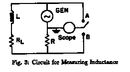
- 1. Set up the circuit shown in Fig. 3. The signal generator
is to be used for the applied emf and the oscilloscope will be used to measure
 and Io.
The single pole double throw (SPDT) switch allows the oscilloscope to be
connected either across the output of the generator (position A) or across the
resistance R (position B). Note the ground of the generator and the ground
of the oscilloscope should be connected together. The vertical input of the oscilloscope
is connected to the pole of the switch. Use a standard 10 ohm resistor for the resistance R.
It should be approximately the same as RL .

- 2. Check the calibration of the oscilloscope (see pg.
61-sec. II).
- 3. Set the frequency of the signal generator to
 =100 Hz
and throw the switch to position A with the oscilloscope input scale (3) set
on the 1 scale. Adjust the amplitude of the signal generator to get as long a line
as possible. Measure the amplitude
  of the applied signal. The output of the signal
generator changes with frequency, so this adjustment has to be made for every frequency
used. Now throw the switch to position B and read the p-p voltage VR
across the resistance R. Note the amplitude of the voltage across R will be VR/2.
It may be necessary to reset the VOLTS/CM scale to a smaller range to be able to
read this voltage. The amplitude of the current will then be Io = (VR)/(2R)
. Repeat these measurements for several (10) frequencies between 100 and
3500 Hz. Tabulate your data.
- 4. Calculate
 and plot as a function of
  . Determine
the slope of this line and calculate L (see equation (2)).
[ purpose | theory I | theory II | procedure | questions ]

