Purpose: The effect of a magnetic field on the trajectory of electron will be observed and a determination of e/m for non-relativistic electrons will be made.
Supplies: Note paper, graph paper, and calculators.
Reference: Halliday, Resnick and Krane, Physics, Chapter 34.2.
A charged particle moving in a magnetic field experiences a force F given by
![]() (1)
(1)
where q is the charge of the particle, ![]() is the particle' s
velocity, and
is the particle' s
velocity, and ![]() is the magnetic field.
If
is the magnetic field.
If ![]() is perpendicular to
is perpendicular to ![]() , the resultant trajectory is circular with a radius of curvature
given by
, the resultant trajectory is circular with a radius of curvature
given by
![]() (2)
(2)
where m is the mass of the charged particle. The charge of an electron is particularly important and therefore it has its special symbol: e . If an electron, initially at rest, is accelerated through an electric potential difference V, then the kinetic energy after the acceleration is equal to the change of the potential energy: qV. From the conservation of energy principle we know that
![]() (3)
(3)
Eliminating velocity v from Eqs. (2) and (3), and substituting the magnitude of the electron charge e for q, we obtain
![]() (4)
(4)
To calculate the e/m ratio we need to know the accelerating potential V, the value of the magnetic field B and the radius of the circular path of the electron beam (it is hard to detect a single electron, therefore we will use a beam of electrons with approximately the same kinetic energy).
Experimental Method-Apparatus
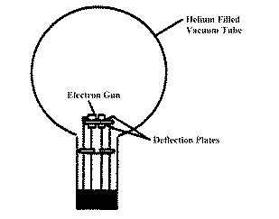
A beam of electrons is produced by an electron gun composed of a filament surrounded by
a coaxial anode (i.e., electrode with a positive charge). Electrons thermally emitted from
the heated filament are accelerated by a known potential difference V between the
filament and the anode. The kinetic energy and velocity of accelerated electrons may be
calculated using Eq. (3). The e/m tube is filled with helium gas at a pressure of ![]() mm Hg (approx. 100,000 times smaller than
the atmospheric pressure). The electron beam leaves a visible trail in the tube, because
some of the electrons collide with helium atoms, which are excited and then radiate
visible light.
mm Hg (approx. 100,000 times smaller than
the atmospheric pressure). The electron beam leaves a visible trail in the tube, because
some of the electrons collide with helium atoms, which are excited and then radiate
visible light.

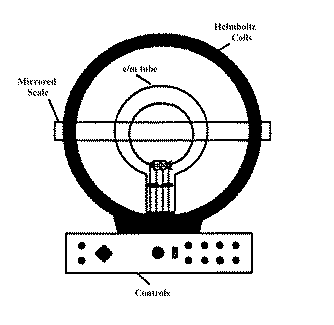
Figure 1. The e/m apparatus (side view).
CAUTION: The voltage to the heater of the filament should never exceed 6.3 volts. Higher voltage will burn out the filament and destroy the e/m tube.
The method is similar to that used by J.J. Thompson in 1897. A pair of Helmholtz coils produces a uniform and measurable magnetic field at right angles to the electron beam. This magnetic field deflects the electron beam in a circular path. By measuring the accelerating potential, the current to the coils, and the radius of the circular path of the electron beam, e/m is easily calculated from Eq.(4).

Figure 2. The e/m tube.
Experimental Equipment
The geometry of Helmholtz coils - the radius of the coils is equal to their separation - provides a highly uniform magnetic field. The Helmholtz coils of the e/m apparatus have a radius and separation of 0.15 m. Each coil has 130 turns. The magnetic field (B) produced by the coils is proportional to the current through the coils (I) and is given by the following formula
![]() (5)
(5)
where N is the number of turns in each Helmholtz coil, a is the
radius of the coils in meters (a = 0.15 m), and m 0
is the permeability of free space (![]() ).
).
The field constant for these coils, k = B/I (in T/A), gives the measure of how many teslas we would get from 1A current through the coils. The `A' wall outlet is to 9V DC and powers the Helmholtz coils. Using the current adjust knob of the e/m apparatus you can change the value of the current through coils in the range of 0 - 2A.
The power supply (made by Sargent-Welch) provides two necessary voltages:
The control panel of the e/m apparatus is straightforward. All connections are labeled. A mirrored scale is attached to the back of the rear Helmholtz coil. It is illuminated by an automatic lamp that is actuated when the heater of the electron gun is powered. By lining the electron beam up with its image in the mirrored scale, you can measure the radius of the beam path without parallax error.
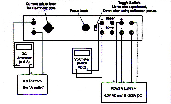
The Fig. 3 shows the electrical connections for the e/m apparatus.
Experimental Procedure

Figure 3. Electrical connections for e/m apparatus.
Here are some items that should be included in your lab report for this experiment.