Physics 536 - Spring 2008
Electronic Techniques for Research
Using Berkeley SPICE with nanoHUB
Introduction
SPICE is a general-purpose circuit simulation program for nonlinear DC,
nonlinear transient, and linear AC analysis. It was developed at the
University of California, Berkeley. Circuits may contain resistors,
capacitors, inductors, mutual inductors, independent voltage and current
sources, four types of dependent sources, transmission lines, and the
four most common semiconductor devices: diodes, BJT's, JFET's, and MOSFET's.
SPICE is freely available and can be installed on most UNIX-like platforms
and can be downloaded from
ftp://sunsite.unc.edu/pub/Linux/apps/circuits/spice3f5sfix.tar.gz
but it is not trivial to run this under Windows. Instead, for Physics 536
we will use a web-based interface to SPICE using nanoHUB.
To use this you will need to follow these instructions:
- Visit nanoHUB and click on 'Register' near the top
of the page.
- Pick a user name and password and fill in your login and contact information.
The personal information you are asked for is used to collect statistics
for reports to the funding agencies that support nanoHUB.
- Once your account is created, log in and go the the page for the SPICE simulation tool:
http://www.nanohub.org/tools/spice3f4/
- On that page is a link
to a demonstration
- It may be helpful to allow pop-ups from the www.nanohub.org in your web browser.
- You may wish to print out the manual.
- Work through the example below:
Example of a simple DC analysis
Consider the circuit shown below:
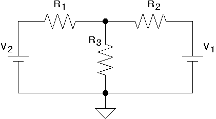 In which the components have the following values:
| Component | Value |
|---|
| V1 | 5 V |
| V2 | 10 V |
| R1 | 10 Ω |
| R2 | 20 Ω |
| R3 | 5 Ω |
The goal is to determine the current flowing through each resistor.
Step 1
Simulating this circuit using SPICE requires translating the schematic into a
representation that can be interpreted by the SPICE program. This representation
is called a netlist and is constructed by the following sequence of steps.
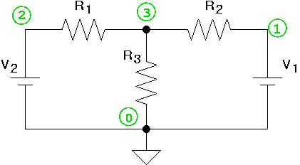
First, number the nodes in the circuit, with ground always assigned '0'.
A node is any point in the circuit that is electrically equivalent. Two parts
of the circuit are electrically equivalent if there are no components between
them through which current must flow (except, of course, an idealized wire).
The result might look like this:
Step 2
The netlist lists the components in the circuit and specifies which nodes they
are connected to. In this case, the circuit contains only resistors and
voltage sources. In their simplest form, these are represented in the netlist
by lines of the form
Rxxxxxx N1 N2 <VALUE>
and
Vxxxxxx N+ N- DC <VALUE>
where N1 and N2 are the nodes on each end of the resistor
and N+ and N- are the nodes at the positive and negative
end of a voltage source, respectively. Following these examples, the circuit
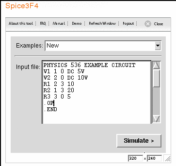
is completely described by a netlist that looks like this:
   V1 1 0 DC 5V
   V2 2 0 DC 10V
   R1 2 3 10
   R2 1 3 20
   R3 3 0 5
Step 3
Although the netlist is the basis for simulating the circuit, SPICE requires
some minor additions including a title line, lines to indicate what simulation
is to be performed, and a line to indicate the end of the input file. In this
case the .OP line indicates that the DC operating point of the circuit
will be determined.
The complete input file that is needed to simulate this circuit using SPICE
would look like this:
   PHYSICS 536 EXAMPLE CIRCUIT
   V1 1 0 DC 5V
   V2 2 0 DC 10V
   R1 2 3 10
   R2 1 3 20
   R3 3 0 5
   .OP
   .END
Step 4
Go to the nanoHUB SPICE web page.
Make sure to log in and click on the 'Launch Tool' button on the right.
Type the SPICE input file into the input window and click on the 'Simulate' button:
Step 5
Fix any errors... read the error messages carefully, consult the manual to make
sure the syntax is correct, check that the netlist is a correct representation of
the circuit you are analyzing, etc...
Step 6
Examine the output:
Circuit: PHYSICS 536 EXAMPLE CIRCUIT
--------------------------------------------------------------------------
PHYSICS 536 EXAMPLE CIRCUIT
V1 1 0 DC 5V
V2 2 0 DC 10V
R1 2 3 10
R2 1 3 20
R3 3 0 5
.OP
.options nopage
.END

--------------------------------------------------------------------------
Note: no resource usage information for 'space',
	or no active circuit available

Circuit: PHYSICS 536 EXAMPLE CIRCUIT

Circuit: PHYSICS 536 EXAMPLE CIRCUIT
Date: Tue Dec 18 10:40:31  2007


Operating point information:

	Node	Voltage
	----	-------
	V(3)	3.571429e+00
	V(2)	1.000000e+01
	V(1)	5.000000e+00

	Source	Current
	------	-------

	v1#branch	-7.14286e-02
	v2#branch	-6.42857e-01

 Resistor models (Simple linear resistor)
 model             R

       rsh         0
    narrow         0
       tc1         0
       tc2         0
      defw     1e-05

 Resistor: Simple linear resistor
 device           r3        r2        r1
 model             R         R         R
resistance         5        20        10
         i     0.714    0.0714     0.643
         p      2.55     0.102      4.13

 Vsource: Independent voltage source
 device           v2        v1
        dc        10         5
     acmag         0         0
         i    -0.643   -0.0714
         p      6.43     0.357

CPU time since last call: 0.006 seconds.

Total CPU time: 0.006 seconds.
Step 7
Think about what it means... In this case the output indicates that the following
currents flow from the voltage sources and through the resistors:
| Component | Value | Current |
|---|
| V1 | 5 V | 71.4 mA |
| V2 | 10 V | 643 mA |
| R1 | 10 Ω | 643 mA |
| R2 | 20 Ω | 71.4 mA |
| R3 | 5 Ω | 714 mA |
This should make sense because all the current flowing out of V1 must
pass through R2 and all the current flowing out of V2 must
pass through R1. The current flowing through R3 must be the
sum of these two currents (and you can check that it is). Note that currents
flowing through voltage sources are presented as current flowing into the
positive terminal and hence are listed as negative quantities in the SPICE output
in this case.