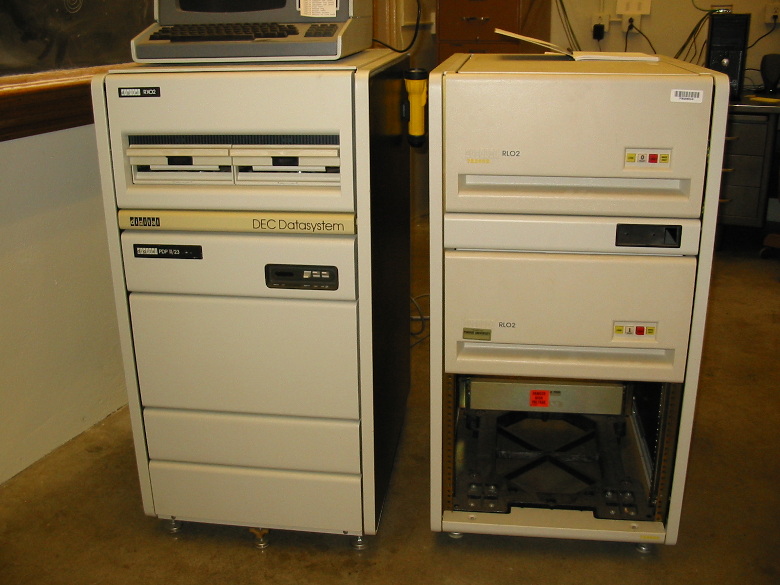
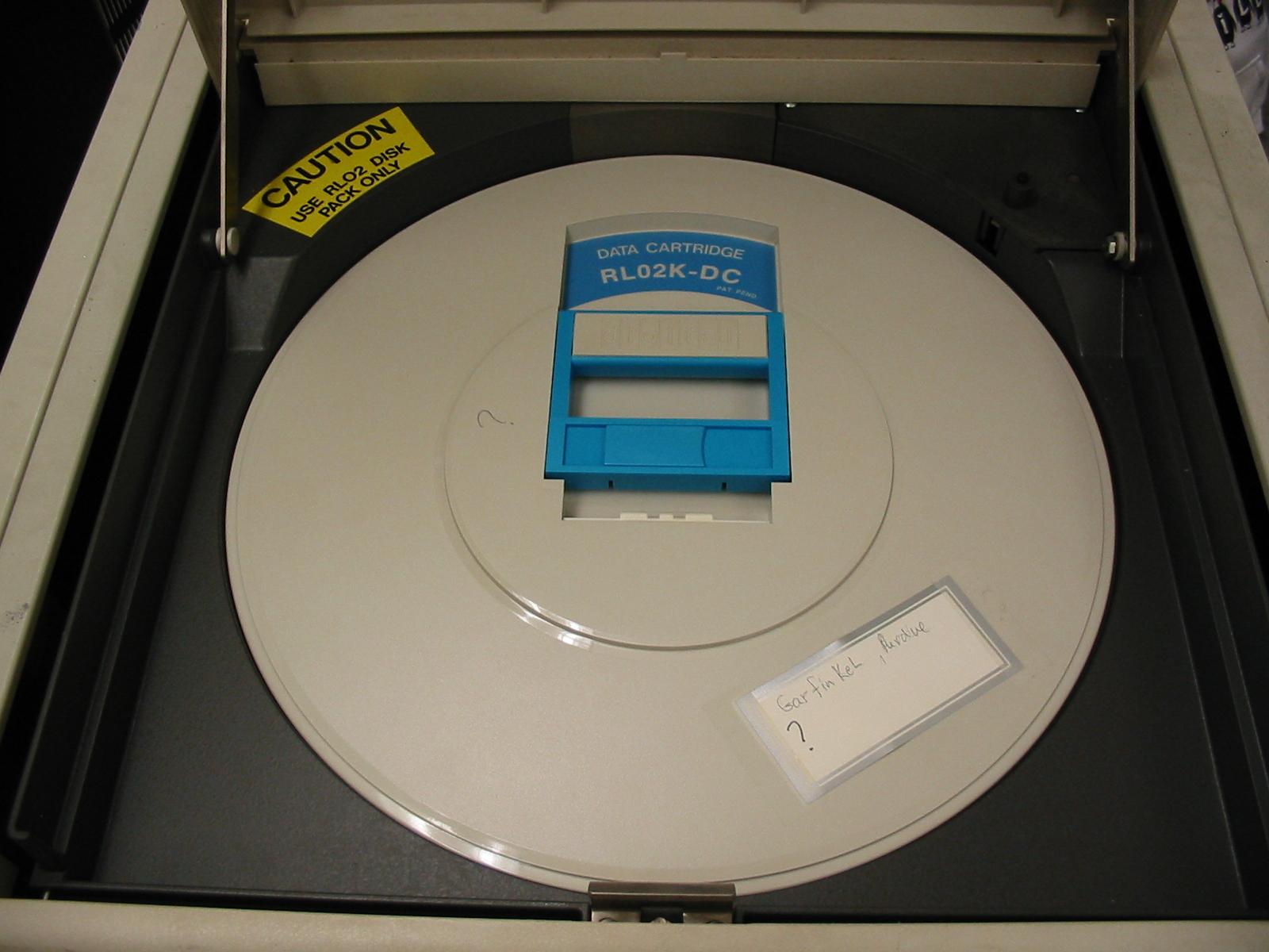
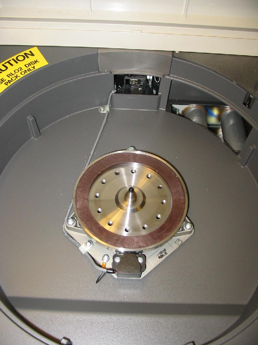
On the left is the PDP-11/23 itself and an RX02 dual 8 inch floppy drive. On the right are two RL02 drives.
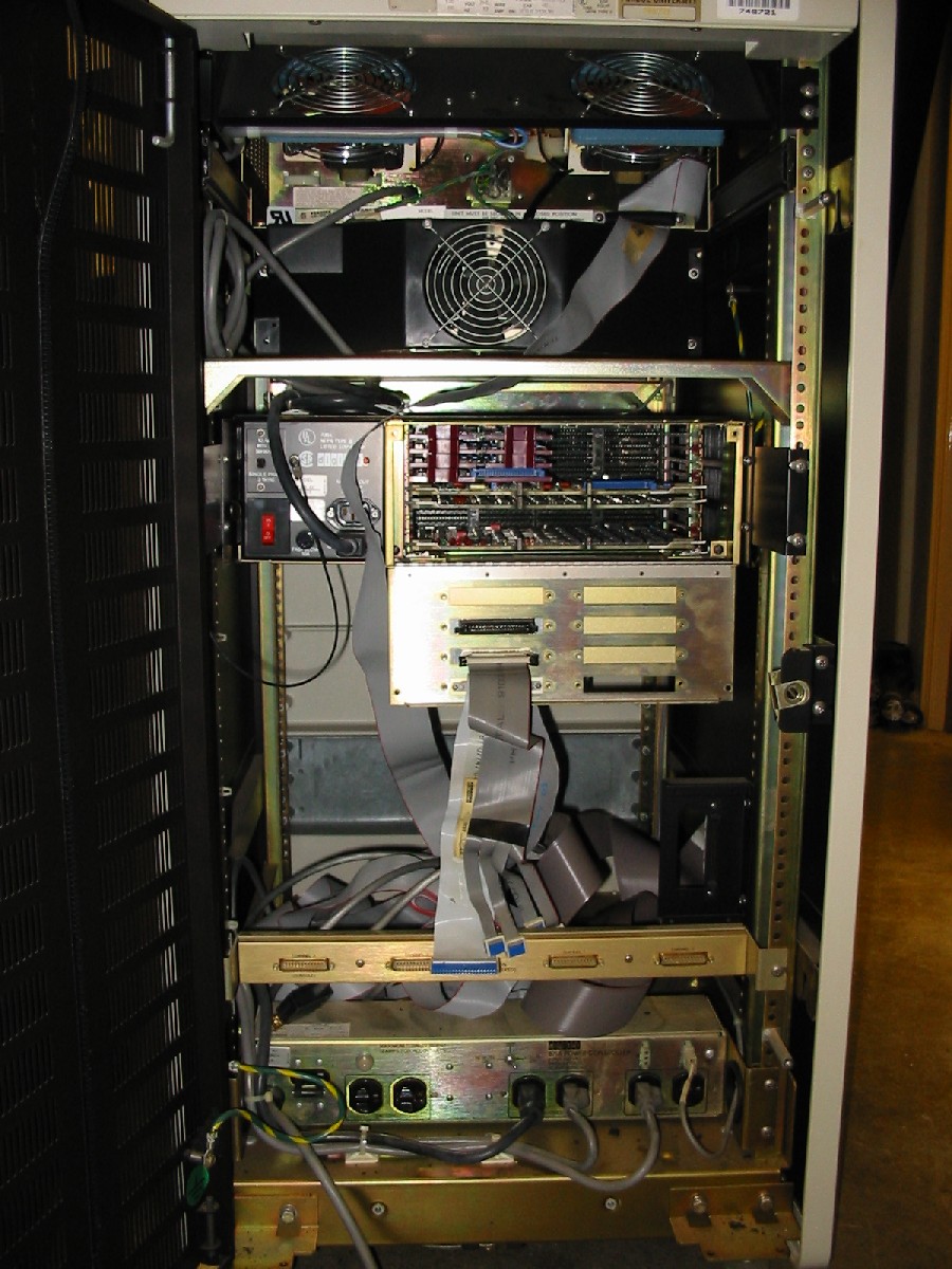
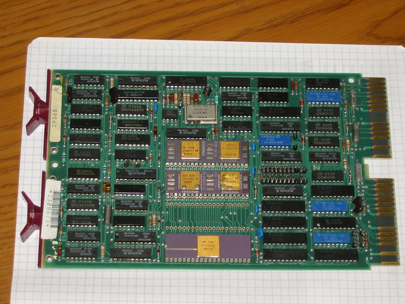
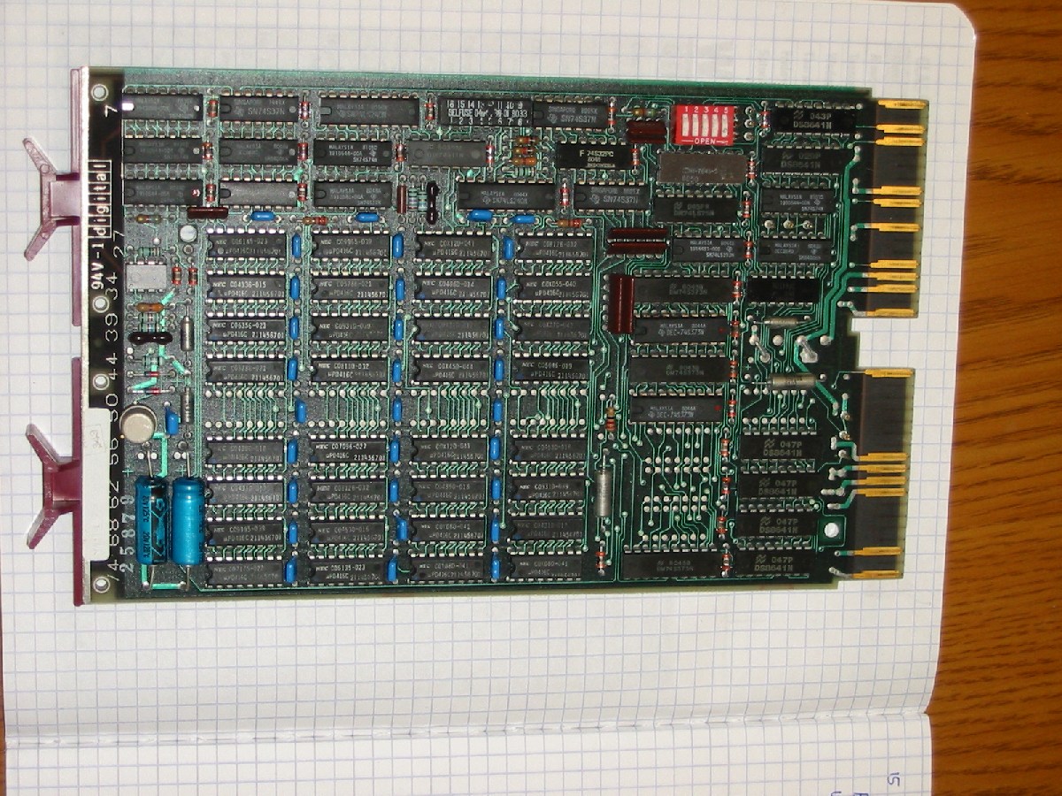
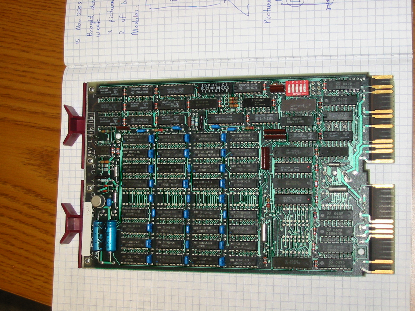
From the back one can see the modules plugged into the QBus backplane. From top to bottom they are:
| M8186 | KDF11-A | QBus 11/23 CPU, 18-bit addressing |
| M8044-DH | MSV11-DD | QBus 32-kWord 16-bit MOS RAM |
| M8044-DH | MSV11-DD | QBus 32-kWord 16-bit MOS RAM |
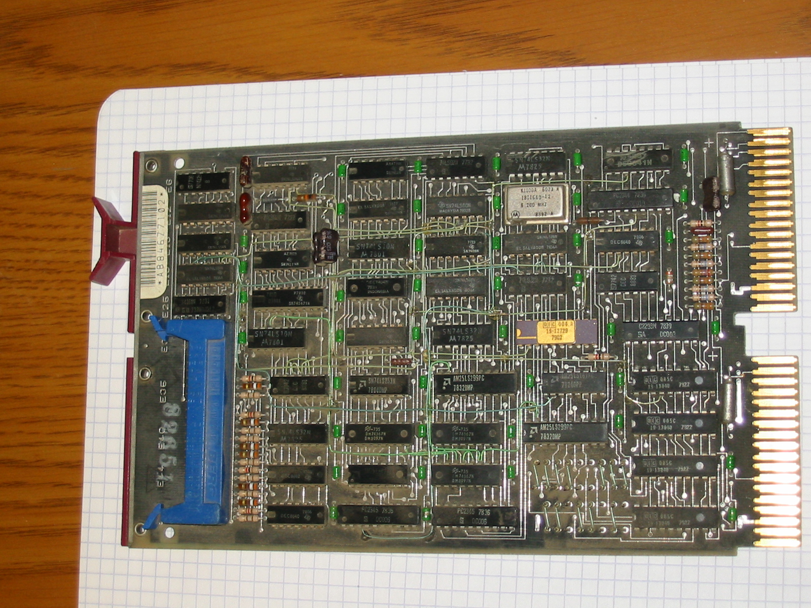
| M8029 | RXV21 | QBus RX02 floppy disk controller |
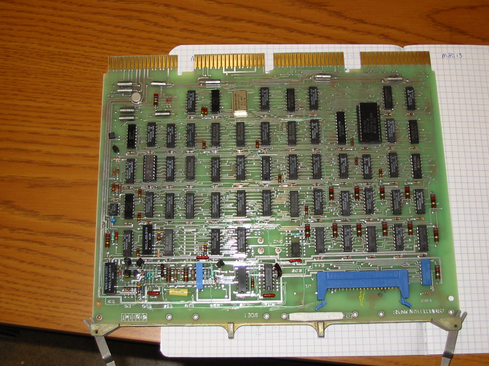
| M8013 | RLV11 | QBus RL01/02 disk controller, 1 of 2 |
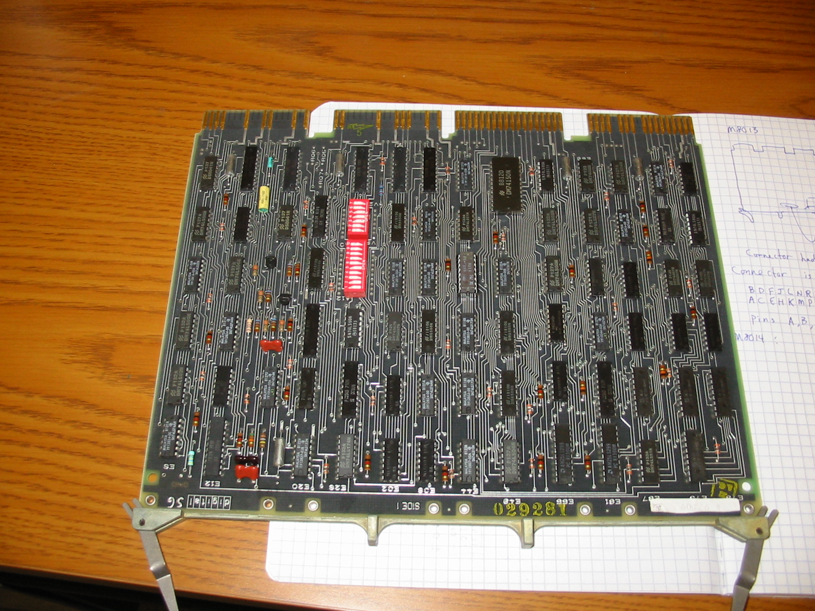
| M8014 | RLV11 | QBus RL01/02 disk controller, 2 of 2 |
| empty | ||
| empty | ||
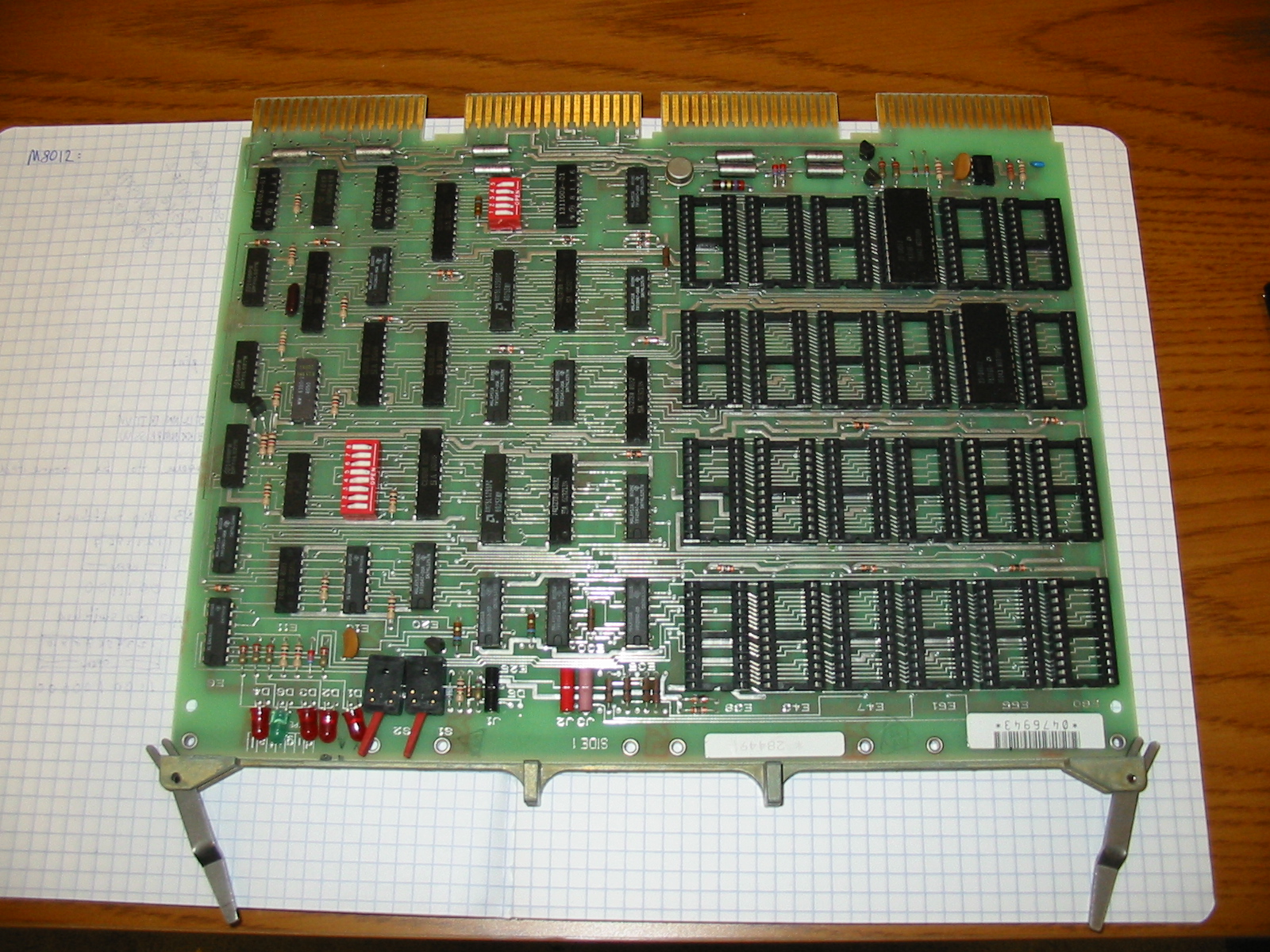
| M8012 | BDV11 | QBus bus terminator, bootstrap and diagnostic ROM |
Unfortunately, there is no DLV11 serial line unit and it will be hard to learn very much without one. More on this later...

Here is an online Operation Manual. Initially, the vertical refresh timing was bad, so that the bottom row appeared in the middle of the screen and stuff would scroll off the top and re-emerge on the bottom. Opening it up reveals the following...
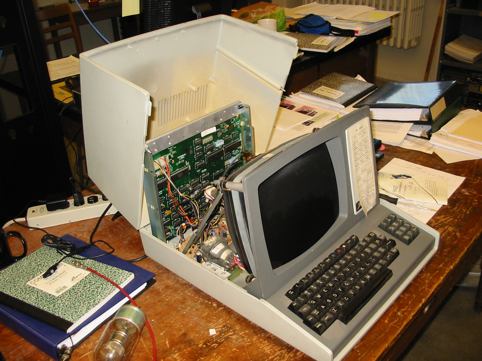
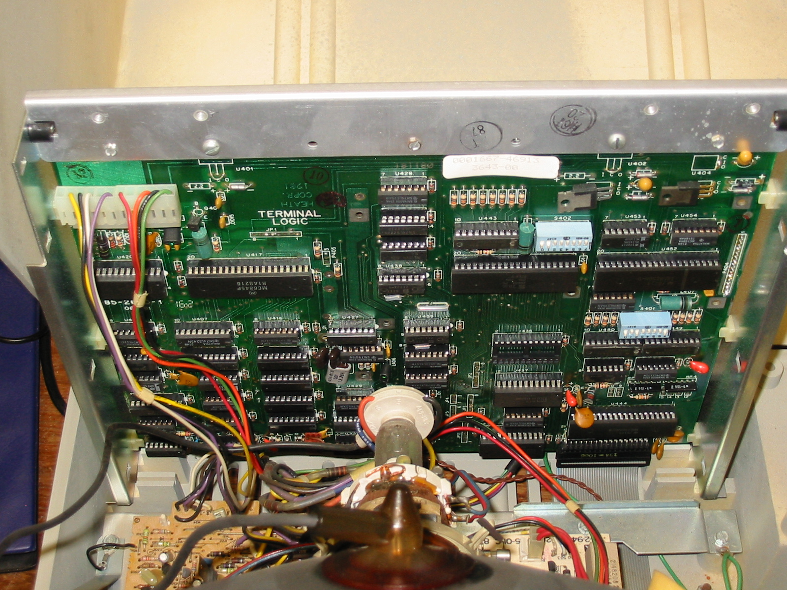
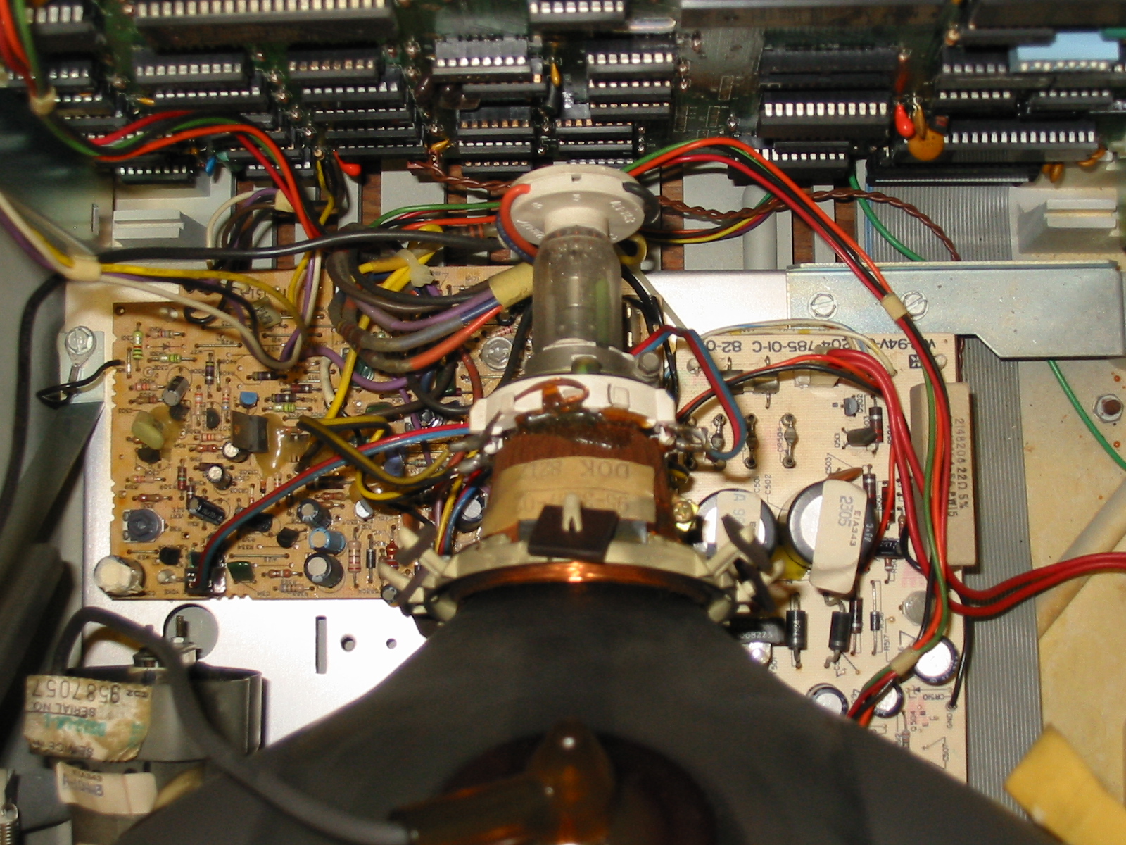
The logic board, mounted vertically, is based around a Z80 processor, which is the middle 40-pin DIP. The left-most 40-pin DIP is a MC6845 video controller, while the other two are a keyboard decoder and an NS8250 asynchronous communication element (ie, a UART). The horizontal PC boards are the power supply on the right and the analog video driver on the right. This has potentiometers for focus, vertical, horizontal and brightness adjustment. Nothing was obviously broken, and after polishing the tarnished ground connections, straightening some of the electrolytic capacitors and repositioning some of the cabling, the vertical sync problem went away and hasn't returned.
This is WAY nicer than the VT50's that came with the PDP-11/03. If I recall correctly, the VT50 had 80 columns but only 12 rows of characters and it was upper case only.
The cables from the DLV-11 go to a H3171-A distribution panel. Using Digi-Key parts 046-0003-ND, 046-0009-ND and A2662R-14-ND, I wired up a cable to interface with the serial port on a server running Linux.
I inserted a random 8" floppy disk (ie, definitely not a boot disk) in the right-hand drive of the RX02 (drive 0) and hit the restart switch. Giving DY0 at the prompt gives:
@
 28
START? DY0
173712
@
So it looks like it would boot if I had a boot disk. The FAULT lights are still lit on the RL02 drives so I don't expect to be booting from them until I figure that out. Meanwhile, there is a lot that can be learned by playing in ODT...
The first test to see if anything is working is just to print a character (an asterisk, octal 052) on the console:
  HACRO V0.3 Monday 12-Dec-2009 05:45

     1                  ;
     2                  ;  First test - print a single character.
     3                  ;
     4                             RCSR=177560          ; DLV11-J console base addresses
     5                             RBUF=177562
     6                             XCSR=177564
     7                             XBUF=177566
     8
     9                             .=1000
    10  001000  112701             MOVB  #052,R1
                000052
    11  001004  105737  $1:        TSTB  @#XCSR
                177564
    12  001010  001775             BEQ   $1
    13  001012  110137             MOVB  R1,@#XBUF
                177566
    14  001016  000000             HALT
    15                             .END

      ERRORS : 0
    WARNINGS : 0
Enter the data into memory using ODT:
@1000/000000 112701
001002/000000 52
001004/000000 105737
001006/000000 177564
001010/000000 1775
001012/000000 110137
001014/000000 177566
001016/000000 0
@
and running it gives:
@1000G*
001020
@
The asterisk after the 'G' is what got printed... so it works well enough to keep going.